Arduino Robot Project: Part 4 - Shield and Software
Arduino Robot Project: Part 4 - Shield and Software
Jul 31, 2017
Gerardo Ramos
Adding Headers to the Motor Shield:
So I finally came across some stackable headers that I ordered from Karlsson Jupiter. I ordered them online and they were available for pick up the next day. The headers came in a 6 pin header, two 8 pin headers, and one 10 pin headers so they connect directly to the Arduino. The headers are important so the Arduino can communicate with the shield. Since I do not know which pins are being used to communicate with the shield, it was important for me to get the whole complete kit. The headers are the stackable kind so I can still connect things on top such as the sensor reading wires from the sensor board. So I placed the headers through the holes of the shield and just soldered one pin from each header.
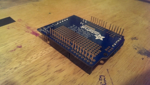
Once I did that, I went ahead and stacked it on top of the Arduino to make sure that the headers were aligned well and that they go into the pins of the Arduino perfectly. If not, I had to reheat to solder to adjust the position of the header. When I checked, all my headers were aligned well. So, I removed the shield carefully and finished soldering the headers onto the shield.

So now it was time to go ahead and start making the connections of the line follower. I restacked the shield again on top of the Arduino. Afterwards, I connected the left motor to the shield where it says M1. I used two jumper cables to connect the end of the wires from the servo to the shield since the servo’s end wires weren't going to be able to connect through the holes of M1. I did the same thing with the right motor but connected to where it says M3 as shown in the picture below. When making these connections, don't insert any of the wires into the port where it says GND. Just use the two ports directly underneath the scripts of the motors. I didn't know which of the two wires would to what port since they may spin in the opposite direction once they are powered but I will not until everything is powered on and working. The blue wires from the sensor, I connected them on top of the shield at the analog pins from analog pin 0 to analog pin 4. The most left sensor would go into analog pin 0. The sensor next to the most left would go into analog pin 1. The middle sensor would go into analog pin 2 and so forth for the two sensor wires. For the power wire of the sensor board, I connected it directly to the regulated 5V pin on the Arduino. The green wire was connected to one of the ground pins next to the regulated 5V pin.
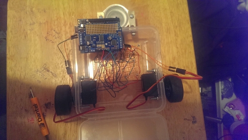
Now to power this robot, I decided to use two separate power sources for the Arduino and for the motor shield since I've online that sharing a power source can sometimes create some problems. For the Arduino, I used a 9V battery to connect through the barrel jack that came with it. For the motor shield, I got my hands on a battery case that I borrowed from my school. The case holds 6 AA batteries that would a final 9V to the motor shield. From reading online, you cannot use a regular 9V battery such as the one I am using for the Arduino. The recommended voltage for the motor shield is 5 to 12 volts so 9 volts is okay. I connect the battery case on the shield where it reads power. In the picture below, all my connections are done. Just that I have not completed the battery connections for the Arduino or the motor shield.
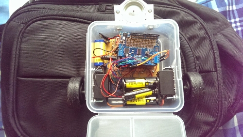
I placed the Arduino on top of the sensor board. I decided to put electrical tape underneath the Arduino as a precaution to avoid any short circuiting of the sensor board and of the Arduino. The battery pack for the motor shield was placed towards the back of the frame as shown. The 9V battery for the Arduino was placed to the side as shown. With the case closed:

The Programming:
For the programming of the Arduino, I first got a code that was already prewritten for the line follower using this setup.
The link to the code is: https://sites.google.com/site/arduinorobotics/home/chapter4_files
But this code was used for an older version of the shield that I am using. So I had to make just a few changes to make the code work. But first I had to download the library for the motor which was found on the website where I ordered the shield from, Adafruit.com. Once the library is downloaded, it is important to copy it to the Arduino's libraries folder. So that's what I did. After copying the library, I made the changes to the code from the link above.
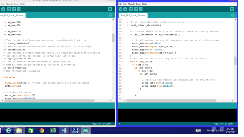
The code is:
// Linus the Line-bot
// Follows a Black line on a White surface(poster-board and electrical type or the floor and tape).
// Code by JDW 2010 - feel free to modify.
// Modified by Gerardo Ramos March 11, 2014
// My first arduino project, first electronic project
#include <Wire.h>  // this includes the Afmotor library for the motor-controller
#include <Adafruit_MotorShield.h>
#include "utility/Adafruit_PWMServoDriver.h"

Adafruit_MotorShield AFMS = Adafruit_MotorShield();


Adafruit_DCMotor *motor_left=AFMS.getMotor(1);  // attach motor_left to the Adafruitmotorshield M1
Adafruit_DCMotor *motor_right=AFMS.getMotor(3);  // attach motor_right to the Adafruitmotorshield M3

// Create variables for sensor readings
int sensor1 = 0;
int sensor2 = 0;
int sensor3 = 0;
int sensor4 = 0;
int sensor5 = 0;

// Create variables for adjusted readings
int adj_1=0;
int adj_2=0;
int adj_3=0;
int adj_4=0;
int adj_5=0;

// You can change the min/max values below to fine tune each sensor
int s1_min=200;
int s1_max=950;

int s2_min=200;
int s2_max=950;

int s3_min=200;
int s3_max=950;

int s4_min=200;
int s4_max=950;

int s5_min=200;
int s5_max=950;

// This threshold defines when the sensor is reading the black line
intlower_threshold=80;
// Value to define a middle threshold(half of the total 255 value range)
int threshold=110;
// This threshold defines when the sensor is reading the white poster board or
// the floor if you are testing it on the floor like I did.
intupper_threshold=200;
// This value sets the maximum speed of linus (max=255).
// using a speed potentiometer will over-ride this setting.
intspeed_value=220;
// End of changeable variables

void setup()
{
Serial.begin(9600);  // Start serial monitor to see sensor readings
AFMS.begin();

  // declare left motor
motor_left->setSpeed(255);
motor_left->run(RELEASE);

  // declare right motor
motor_right->setSpeed(255);
motor_right->run(RELEASE);
}

voidupdate_sensors(){

  // This will read sensor 1
  sensor1=analogRead(0);
  adj_1=map(sensor1,s1_min,s1_max,0,255);
  adj_1=constrain(adj_1,0,255);

  // This will read sensor 2
  sensor2=analogRead(1);     // sensor 2 =left-center
  adj_2=map(sensor2,s2_min,s2_max,0,255);
  adj_2=constrain(adj_2,0,255);

  // This will read sensor 3
  sensor3=analogRead(2);   // sensor 3 =center
  adj_3=map(sensor3,s3_min,s3_max,0,255);
  adj_3=constrain(adj_3,0,255);

  // This will read sensor 4
  sensor4=analogRead(3);  // sensor 4 = right-center
  adj_4=map(sensor4,s4_min,s4_max,0,255);
  adj_4=constrain(adj_4,0,255);

  // This will read sensor 5
  sensor5=analogRead(4);   //sensor5 = right
  adj_5=map(sensor5,s5_min,s5_max,0,255);
  adj_5=constrain(adj_5,0,255);

}

void loop(){
update_sensors();  // update the sensors

  // First, check the value of the center sensor
if (adj_3<lower_threshold){

    // If center sensor value is below threshold, check surrounding sensors
if (adj_2>threshold && adj_4>threshold){

      // If all sensors check out(if statements are satisfied), drive forward
motor_left->run(FORWARD);
motor_left->setSpeed(speed_value);
motor_right->run(FORWARD);
motor_right->setSpeed(speed_value);
    }
    // You want the line bot to stop when it reaches the black box/
else if (adj_1<30){
if (adj_2<30){
if (adj_3<30){
if (adj_4<30){
if (adj_5<30){

              // Here all the sensors are reading black, so stop the bot.
motor_left->run(RELEASE);
motor_right->run(RELEASE);
            }
          }
        }
      }
    }
  }
  // Otherwise, the center sensor is above the threshold
  // So we need to check what sensor is above the black line
else {
    // First check sensor 1
if (adj_1<upper_threshold&& adj_5>upper_threshold){
motor_left->run(RELEASE);
motor_left->setSpeed(0);
motor_right->run(FORWARD);
motor_right->setSpeed(speed_value);
    }

    // Then check sensor 5
else if (adj_1>upper_threshold&& adj_5<upper_threshold){
motor_left->run(FORWARD);
motor_left->setSpeed(speed_value);
motor_right->run(RELEASE);
motor_right->setSpeed(0);
    }

    // If not sensor 1 or 5, then check sensor 2
else if (adj_2<upper_threshold&& adj_4>upper_threshold){
motor_left->run(RELEASE);
motor_left->setSpeed(0);
motor_right->run(FORWARD);
motor_right->setSpeed(speed_value);
    }

    // if not sensor 2, then check sensor 4
else if (adj_2>upper_threshold&& adj_4<upper_threshold){
motor_left->run(FORWARD);
motor_left->setSpeed(speed_value);
motor_right->run(RELEASE);
motor_right->setSpeed(0);
    }
  }

  ///// Print values for each sensor
  ///// Sensor 1 values
Serial.print("Sensor 1:  ");
Serial.print(sensor1);
Serial.print(" - ");

Serial.print("Adj 1:  ");
Serial.print(adj_1);
Serial.print(" - ");

  // Sensor 2 Values
Serial.print("Sensor 2:  ");
Serial.print(sensor2);
Serial.print(" - ");

Serial.print("Adj 2:  ");
Serial.print(adj_2);
Serial.print(" - ");

  // Sensor 3 Values
Serial.print("Sensor 3:  ");
Serial.print(sensor3);
Serial.print(" - ");

Serial.print("Adj 3:  ");
Serial.print(adj_3);
Serial.print(" - ");

  // Sensor 4 Values
Serial.print("Sensor 4:  ");
Serial.print(sensor4);
Serial.print(" - ");

Serial.print("Adj 4:  ");
Serial.print(adj_4);
Serial.print(" - ");

  // Sensor 5 Values
Serial.print("Sensor 5:  ");
Serial.print(sensor5);
Serial.print(" - ");

Serial.print("Adj 5:  ");
Serial.print(adj_5);
Serial.print(" ");

}

// End of this code
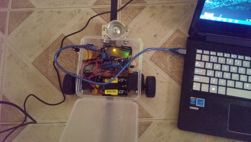
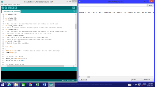
Once I completed the code, I connected my Arduino to my laptop. Then I reopened the code, then compiled to make sure there were no errors. Then I uploaded the code to the Arduino. At this I didn’t have the motor shield powered. So in this way I can see what the sensors are reading. To do this I opened the serial monitor. Turn off autoscroll so you can see what the sensors are reading. So I placed the line follower on the floor to see what it reads. For me, it read the floor at high readings at 255 which is good. It means that it’s reading it as it were a white poster board. I didn’t have a large poster board to test the Arduino so I opted to just my floor.

For my lower threshold I used 80. The original code had 20, which was good but sometimes my sensors didn't read long enough to read below 20. So I used 80. Just compare your readings of the black line to your thresholds. You want the reading of the black line to be lower than the lower threshold value. Here I was experimenting with 50 but it didn't really work out well. Sometimes my middle sensor would directly above the black line but would get a reading of sometimes in the 60's. So the if-else statement didn't work well with the line follower going in a straight line. Some of the reasons why it’s not reading a low enough a number is because maybe the sensors or placed to close or maybe the adjacent sensors are directly perpendicular to the floor. So maybe some of their infrared light is being read by the middle sensor. Whatever the reason was, I had to make increase my lower threshold value.
There are times where my readings are as low as 8 but that isn't the case every time. So I increased my lower threshold to 80. And I also increased my threshold value to 110 just to make sure the if-else statements work. I also decreased my upper threshold value to 200 to allow it to account for slightly darker areas of the floor. The speed of the line follower can be chosen from any range from 0 to the maximum of 255. For me, I used 220. Compare your thresholds with the if-else statements to make sure that everything makes sense to and to figure what numbers you should choose for your setup since every setup is going to be slightly different.
Doing a Test Run:
Now after "calibrating" the line follower it was time to do a test run. At first I was doing a small track but the turns were a little too tight. So I did a bigger track. I used black electrical tape for the track. I made sure the tape was flat all around the track to prevent it from being too high and get in the way of the line follower as I have learned doing it a few times.
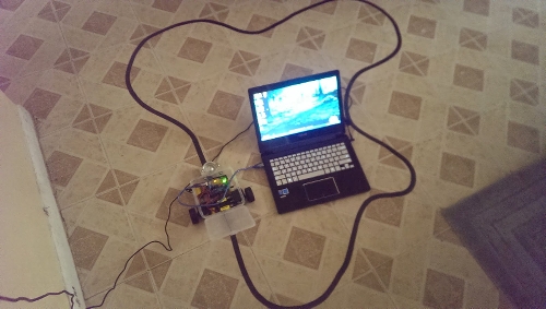
There are times were the line follower does go off track but I think it's because it possibly be reading debris on the ground. Well that is the only explanation I can think off. Another issue that I had was that sometimes the turns could be too tight? Such as the at bottom right of my laptop. I figure that with a smaller frame, the robot can execute the turns much better as I have seen on YouTube videos of racing line followers. Well that's it guys until next where I will have video of the line follower in action.