3D Printed Robotic Hand: Part 3 - The Glove Build
3D Printed Robotic Hand: Part 3 - The Glove Build
Sep 12, 2017
Gerardo Ramos
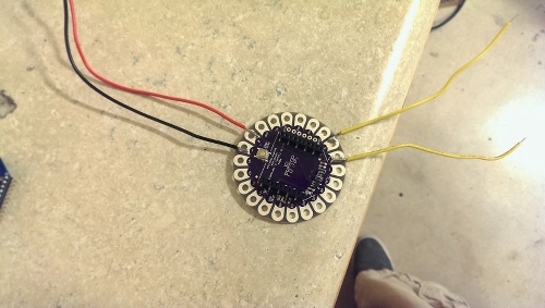
In this post I will be going over the making of the glove that will control the 3D printed hand. I started off by first soldering the 5 47K ohm resistors onto the LilyPad's pads a0, a1, a2, a3, and a4. I also soldered the resistors together as shown in the picture below.

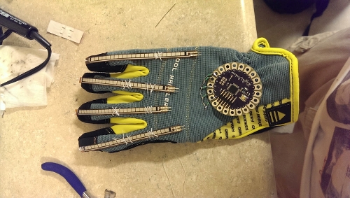
From there I went ahead and started to create holes at the top of each flex sensor by using a needle. I will be sowing through this hole to the glove to create a good attachment to the glove.

After doing that, I went ahead and started sowing the flex sensors onto the glove that I got from Wal-Mart. I sowed where the fingers bend. I learned that if you don't sow it down enough that the sensors will sometimes not go back to being straight flat on the glove. I also sowed the LilyPad onto the glove. But I later cut the threads attaching the LilyPad because I needed some rearrangements of the parts.
I then proceeded with adding wires to make connections between the flex sensors and the LilyPad.
I used red wiring to connect the power pad from the LilyPad to the pinky flex sensor. From there I connected every right pin of each flex sensor together. I used yellow wires to connect the left side connection of each flex sensors to the analog pads. Every time the flex sensors are bending, the resistance will change and that will be read by the analog pins. At the end of the connections of the resistors, I connected a black wire between the last resistor and the negative pad on the LilyPad for ground.

I then went ahead and started working on the LilyPad XBee shield. I just soldered a red and a black wire on the power and negative pads of the shield. I then added two yellow wires that I soldered on the tx and the rx pads. These two yellow wires will be connected to the LilyPad's rx and tx pads. From rx to tx and tx to rx.
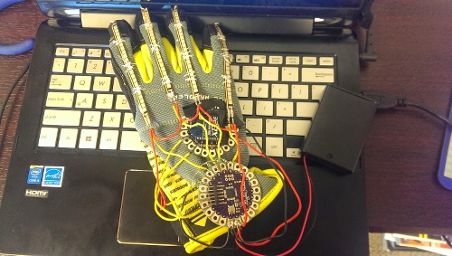
I was running out of room on the glove so I decided to place the XBee shield in between the flex sensors and the LilyPad. A gauntlet style glove would be more ideal since you would have more room to place the components onto. I didn't really thought I would need more space but I was wrong.

I put more threads on the flex sensors to make it more secured. I also added electrical tape on the XBee shield where I see there could be some sort of short circuiting or any type of unintended connections between the shield and the flex sensors. I also soldered the battery pack on the positive and the negative pads of the LilyPad as shown below.
So that's pretty much it for the glove. I'm currently working on assembling the 3D printed. I will have more on that once I have finished assembling the hand.
If you have any questions or would like to know anything about the setup, just drop a comment and I'll try to get back to you as soon as possible.