Vintage Toolbox 3D Printed: Part 1 - Design and Research
Vintage Toolbox 3D Printed: Part 1 - Design and Research
Nov 03, 2017
Chad B.
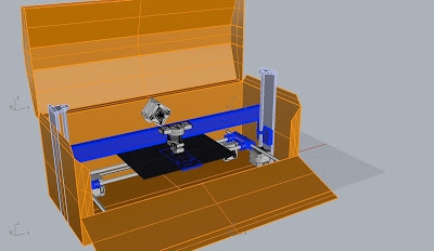
Below is a new project for Boca Bearings where I will be constructing a 3D printer with in a Huot toolbox that was once used as a "Blower Repair Kit."


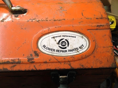
One of the main features that makes this toolbox a good candidate for a printer over other toolboxes is its fold-down front. A spectator is able to view the print from both the top and the front while also allowing extra room for the print bed.
When I begin a design for a printer or other multiple component machine, I do not start in the computer or even a sketch pad because there are too many things going on for me to even know where to start. I find it helpful to begin "mocking up" a model, often using the parts I will be building with such as bearings, pulleys, guide rails, stepper motors, a hot end and spare 3D printed parts from past builds.


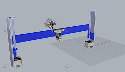
For this build, I began with a piece of scrap ABS plastic cut down to the desired size (6" x 9") of my print bed. I simply position it throughout the toolbox and take some measurements to determine if everything will fit and how I will proceed. I determined that I would use the X and Y-axis to control the bed and the hot end would be controlled by the Z-axis. I created a crude model of the X and Y-axis by using parts I had lying around my studio. The ABS "bed" would be fitted with some linear bearings, precision cut drill rod and some parts from a bin of 3D prints from past builds so I can check the next set of components.
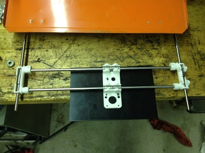


Once the X,Y-axis is placed in the toolbox, I can figure out where the stepper motors might be mounted and make sure I do not have any clearance issues.


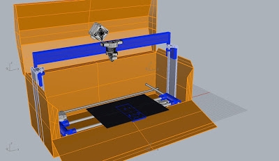
At this point, I have quite a bit of information I can capture in a 3D modeling program such as Rhino. I can begin to tighten my tolerances and capture accurate measurements so I can continue onto the next steps in the design.

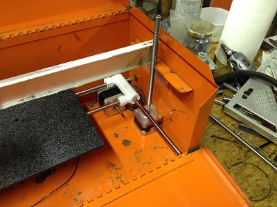
Now that I have the X and Y axis roughly figured out, I can now begin on the Z axis. I now know where the bed is going to be and this will determine where I am able to squeeze in the Z axis. I make any adjustments to my mocked-up tool box and I begin to work with different possible designs. Once again, I use materials from around the shop including a hot end,threaded rod, some extruded aluminum and zip ties to stand in for a gantry that will fit the hot end.

I will again go back into the computer and refine details on the X and Y-axis while figuring out how the Z will move. I will go back and forth throughout the entire build until everything is fulling refined.

Here are some videos describing the project for Boca Bearings.
1. The first gives a basic description of parts being used to mock up a working model.
2. The second video show the development of the printer bed. These parts are only for figuring out the design and will later be refined and printed in the correct color.
3. The third video clip of this build looks at how the hot end will move up and down along the Z-axis. From here, everything will be rendered in Rhino so I can figure out the details of how it will actually move, and then construction will begin.