Simple Robotic Arm Made Out of Cardboard Pieces - Part 2: How to make it
Simple Robotic Arm Made Out of Cardboard Pieces - Part 2: How to make it
Feb 05, 2018
Gerardo Ramos
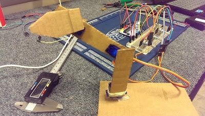
This post I will be covering on how to create a simple robotic arm out of cardboard pieces. This project is fairly simple and based on the Arduino's IDE example "Knob." I will be covering on what parts are necessary and where to get them.
List of Parts
The following parts are necessary to complete this project:
An Arduino Uno -- The Uno can be a genuine Uno or to lower costs you can obtain an Arduino clone that works the same way. You can buy a clone at the following link for about $15:

3 10k Potentiometers - This can be found anywhere such as Amazon, eBay, and Adafruit. Shop around to find cheap prices for them. Any type of potentiometers with at least 3 prongs should be able to work. The ones I used were 22k but 10k potentiometers seem to be cheaper. Just make sure you get linear potentiometers and not a log type. Here are some potentiometers at the following link on eBay:

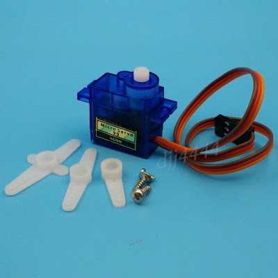
3 Micro Servos (SG90) -- These servos can also be found on eBay for fairly low prices. Just be aware that if you order from China, shipping may take a while. The following link is for 5 servos in the US:
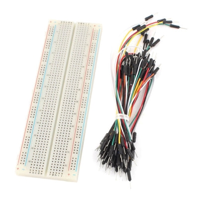
A Breadboard -- The breadboard used in this project was actually bought at my school for $5. But you could probably find a cheap one on eBay. RadioShack sells them but the price could be much higher. The following link is actually for a breadboard that comes with jumper wires.
The only downside is that it's coming from China. But it is inexpensive.
Batteries - A 9V battery can be used to power the Arduino or you can just power it through a USB cable. You will also need a battery pack that fits 4 AA batteries. This battery pack will power the servos.
Jumper Cables/Wires - You will also need some jumper cables/wires to make connections between the Arduino and the breadboard. But if you get them together with the breadboard it will help you with costs and time.
And Cardboard!
Tools
For this project you will need the following tools:
- Pair of scissors
- Razor blade or Box Cutter
- Hot Glue Gun or any other means to glue/hold parts together.
Making the Individual Arms
Now it is time to draw out the arms on a piece of cardboard that you can find around. The dimensions of the three arms can be seen below in the drawings.
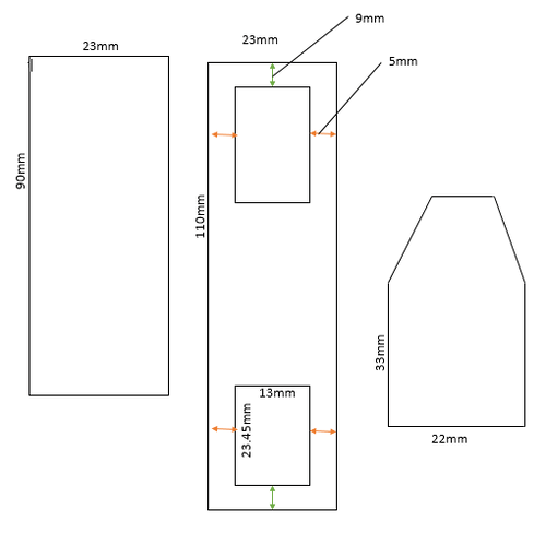
The first arm is the one to the left. This has a height of 90mm with a width of 23mm. The second arm in the middle with the two rectangular cuts inside of it will hold two servos. Each inner cut is 13mm wide with a height of 23.45mm. The edges of these cuts will be 5mm away from the outer edge of the entire arm on the left and right. It will also be 9mm apart from the bottom and the top edge. These distances can be seen by the arrows and their color. Red arrows mean a distance of 5mm while the green arrows mean a distance of 9mm. One thing that I have noticed was that the dimensions marked by red arrows were pretty thin that sometimes the arm would bend. So probably an overall wider width for arm 2 can help with that. Just make sure you have the inner rectangles centered.

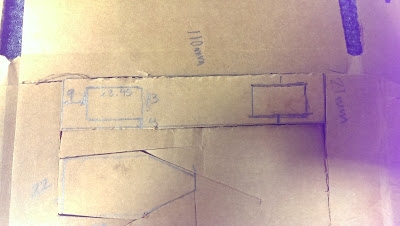
The final arm has only two important dimensions. The width of the third arm at the bottom is 22mm while the height of the left and right side of the arm is 33mm. The other 3 edges can be any length that you would like or any shape.
Once you have drawn the arms out on the cardboard, you can use the pair of scissors to cut them out. The only suggestion I have here is when it comes to cutting out the smaller rectangles in the second arm you should use a razor blade. Using a pair of scissors can be hard to cut them out. The razor blade cuts it more precisely and helps from cutting towards the outer edge of the arm.
One more suggestion would be in making the second arm wider. So instead of using a width of 23mm, try to go a little bigger. The reason for this is that the distance between the smaller rectangles and the outside edge is really small using my first dimension. My first dimension that I used in the video was a width of 21mm. So the distance between the rectangles and the outer edge on the left and right was only 4mm. Later on this caused the arm to bend. So I suggest using a bigger width for the second arm.
Assembling the Arm
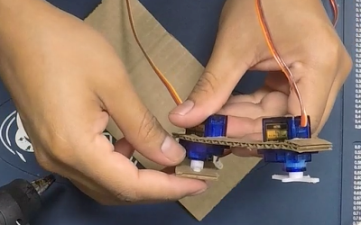
For the first thing to do would be grabbing the second arm and placing two servos inside the two rectangular cuts, as shown below.
After doing that, grab the first arm and attach a servo on its side with a rubber band as shown in the picture below.

Make sure the rubber band is holding the servo firmly against the arm but don't over tighten it. Have the servo horn have some distance away from the cardboard so the arm can rotate about the servo horn. The next step is to then glue this servo horn onto a large base as shown below.

Make sure the base is pretty big so the arm won't topple over when it is in action. The base size I used was about 3 inches by 6 inches. This base wasn't big enough to hold the arm securely. So maybe going with a larger size might help. If not, what I did was used a caliper to weigh down the base. You could probably use coins or something heavy to hold the base securely.
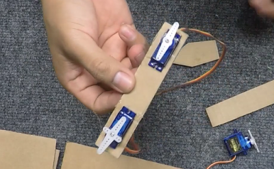
Now the next step would be gluing one of the horns from the second arm to the first arm as shown below.
The horn should be glued with the horn pointing up and down. Before gluing the horn, decide what kind of range you would like your arm to have. The servos provide about 180 degrees for motion. But you can choose where this range can be set at. For example, the way I have set up this arm would allow it to go pretty low but can could move a little past its vertical position. You can get the arm to move from left to right if you place the horn on the servo vertically while the arm is in a 90 degree position to the right. In this 90 degree position, you can place the horn vertically on the servo. When glued onto the first arm in this position, you will be able to rotate the arm from 90 degrees to right to 90 degrees to the left. Again, you can decide this. Just make sure you won't have it its range where its minimum position would be pointed straight downward and its maximum towards straight up. This would cause the arm to go really low to the point where it will interfere with the base/ground.
After gluing the second servo horn onto the first arm, you will do the same with the third arm. You will just simply glue the third arm onto the third servo horn that is being held in the second arm as shown below.

Once that is done, you have completed in making the arm.

Making the Connections
When it comes to making the electronic connections I found a useful program called Fritzing that allows me to display the circuit of the project with clear pictures and wiring. I decided to use this program to show and explain how to make the connections along the way. Hopefully they will be clear enough for anyone to follow.
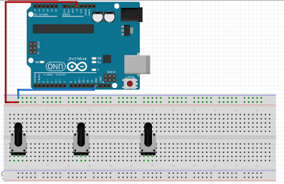
To start off, the potentiometers were placed on the breadboard and an Arduino Uno was placed as right above the breadboard.
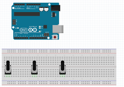
I will try to follow the layout of the parts as the way they were shown in the video. So the 3 potentiometers were placed as shown. Each potentiometer has 3 prongs or connections. In this setup the prong to the left will be connected to the 5V from the Arduino and the prong to the right will be connected to a ground pin on the Arduino. The middle prong for each potentiometer is the signal which will be connected to an analog pin on the Arduino. So what I did next was connect a wire from the 5V pin on the Arduino to the power rail on the top portion of the breadboard and a wire between a ground pin on the Arduino to the negative rail on the breadboard as shown below.
Once that was done, it was time to connect all the left prongs of each potentiometer to the positive rail and the right prongs to the ground rail, as shown below.

For the last prong left on each potentiometer, the middle one, they were connected to a specific analog pin on the Arduino as shown below.

For the first potentiometer to the left, the middle pin was connected to A0 on the Arduino. The second potentiometer has its middle pin connected to A2. The last potentiometer's middle pin was connected to A5. These signal wires will provide the different readings the potentiometer will have during the turning of the knob.
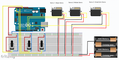
The next step would be to connect an external power source to the breadboard for the servos. The battery pack is connected to the unused bottom rails, as shown below.

The three servos will also have their ground wires connected to the bottom negative rail as shown in the picture above. The ground wires on the micro servos would be the brown wires.The first servo, Servo 1, will be the servo that is glued to the base and connected to the first arm. Servo 2 will be the servo that will be connection between the first and the second arm. Servo 3 will be the last servo that controls the small last arm. It connects arm 2 to arm 3.
Once that is done, it is time to connect the power wires from each servo to the power rail at the bottom. The power wires on each servo will be the red wire. The connections will be as follows:

Once the servos have their power and ground wires connected to the bottom rails, the last thing to do will be connecting their signal wires to the Arduino. In the diagram, these signal wires are yellow. But on the actual micro servos, they are orange wires. So for Servo 1, the signal wire will be connected to pin 9. Servo 2 will be connected to pin 10 and Servo 3 will be connected to pin 11. So the final circuit is as follows.
That is all for the wiring and connections for the simple robotic arm. The last thing to do is to upload the program onto the Arduino. To power the Arduino, you either use the USB cable or a 9V battery to power it.
Uploading the Program
The program for this simple arm is basically the "knob" example that comes in the Arduino's IDE. I just simply added two more servos and potentiometers in the program to be able to control the robotic arm via the potentimeters. So the program to upload on the Arduino is as follows:
/*


Controlling a servo position using a potentiometer (variable resistor)


by Michal Rinott <http://people.interaction-ivrea.it/m.rinott>


modified on 8 Nov 2013


by Scott Fitzgerald


http://arduino.cc/en/Tutorial/Knob


Added two more servos and potentiometers to control the simple robotic arm


-Gerardo Ramos October 26, 2015


*/


#include <Servo.h>


Servo servo1, servo2, servo3;  // create servo objects to control a servo


int potpin = 0;  // analogs pin used to connect the potentiometer

int potpin2 = 2;

int potpin3 = 5;


int val;    // variables to read the value from the analog pin

int val2;

int val3;


void setup()

{

  servo1.attach(9);  // attaches the servo on pin 9 to the servo object

  servo2.attach(10);

  servo3.attach(11);

}


void loop()

{

  val = analogRead(potpin);            // reads the value of the potentiometer

  val = map(val, 0, 1023, 0, 180);     // scale it to use it with the servo between 0 and 180

  servo1.write(val);                  // sets the servo position according to the scaled value


  val2 = analogRead(potpin2);

  val2 = map(val2,0,1023,0,180);

  servo2.write(val2);


  val3 = analogRead(potpin3);

  val3 = map(val3,0,1023,0,180);

  servo3.write(val3);


  delay(15);                           // waits for the servo to get there


}
Once you have uploaded the program, you should be good to go. That pretty much sums up everything for this project. If I have left out anything or have a question just drop a comment and I'll try to get to you as soon as possible.